
We are a small factory specialized in precision machining parts in China, providing various machining services. Material can be carbon steel, alloy steel, stainless steel, copper and other materials. We have CNC lathe, vertical machining center, horizontal machining center, gantry machining center and other commonly used CNC machining equipment.
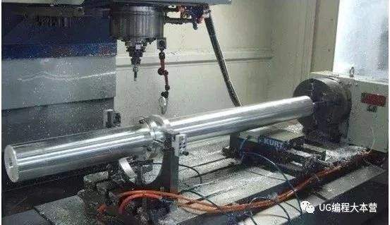
Recently, we have processed a batch of slender shaft parts for American customers, with diameter of 40 mm, length of 1200 mm, material of C45 and quantity of 200 pieces. Slender shaft is a common type of parts in machining. Because of its long and thin, its rigidity is very poor, so it is difficult to machine. You have discussed a lot about the processing methods of long and thin shafts. Here I will share some of my own experience with you, hoping to help you.
1. Select the appropriate clamping method
1.1 Double tips method:With double tips clamping, workpiece positioning is accurate, easy to ensure coaxiality. However, when the slender shaft is clamped by this method, its rigidity is poor, its bending deformation is large, and it is easy to produce vibration. Therefore, it is only suitable for a small ratio of length to diameter, small machining allowance, high requirements for coaxiality and multi-step shaft.

1.2 Clamping method of one clamp and one tip: When using the method of one clamp one top, if the top is too tight, in addition to bending the slender shaft, it can also hinder the thermal elongation of the slender shaft during turning, resulting in the bending deformation of the slender shaft caused by axial extrusion. In addition, the center of the clamping surface of the claw and the center hole may have different axial degrees, which will lead to over positioning after clamping, and also lead to bending deformation of the slender shaft. Therefore, when adopting the clamping mode of one clamp one top, the center should adopt the elastic movable center, so that the slender shaft can stretch freely after being heated to reduce its heating bending deformation; At the same time, an open steel wire ring can be padded between the claw and the slender shaft to reduce the axial contact length between the claw and the slender shaft, eliminate the over positioning during the installation and reduce the bending deformation.

1.3 Double cutting method; When using double cutters to turn long and thin shafts, it is necessary to refit the slide in the lathe, increase the back rest, and use the front and rear cutter to turn at the same time. When turning with two turning tools at the same time, the radial cutting forces generated are mutually offset. The workpiece has small deformation and vibration, high machining accuracy, and is suitable for mass production.

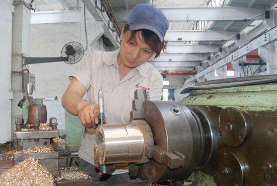
1.4 Adopt the follow-rest and center frame:In order to reduce the bending deformation of slender shaft caused by radial cutting force when turning the slender shaft with the clamping method of one clamp and one top, traditionally we use the tool holder and the center frame, which is equivalent to adding a support on the slender shaft, thus increasing the rigidity of the slender shaft and effectively reducing the impact of radial cutting force on the slender shaft.
This method is used by many small machining factories in China. This time, we also use this method to process slender shafts for American customers.
1.5 1Turning slender shaft by reverse cutting:The reverse cutting method is that the turning tool moves from the main shaft chuck direction to the tailstock direction. In reverse turning, the cutting force on the shaft is the pulling force towards the tailstock, so as to avoid the bending deformation caused by the pressure on the shaft in the forward turning (in the forward cutting, the shaft is pushed towards the chuck by cutting force)
2、Selection of reasonable cutter angle
In order to reduce the bending deformation of the slender shaft, the smaller the cutting force is, the better it is. In the geometric angle of the tool, the front angle, the main deflection angle and the angle of the edge have the greatest influence on the cutting force. The slender shaft turning tool must meet the following requirements: small cutting force, reduced radial component force, low cutting temperature, sharp blade, smooth chip removal and long tool life. It can be seen from the steel turning that: the current angle γ 0 increases by 10 °, the radial force component (fr) can be reduced by 30%; the main deflection angle Kr increases by 10 °, the radial force component( fr) can be reduced by more than 10%; when the angle λ s is negative, the radial force component (fr) also decreases.
2.1 The
front angle (γ 0) directly affects the cutting force, cutting temperature and
cutting power. Increasing the rake angle can reduce the plastic deformation
degree and the cutting force of the metal layer to be cut. Increasing the rake
angle can reduce the cutting force, so in the turning of slender shaft, under
the premise of ensuring the enough strength of turning tool, the rake angle of
the tool should be increased as much as possible, and the rake angle is
generally taken as γ 0 = 150. The front face of the turning tool shall be
equipped with a chip breaking groove, with width b = 3.5-4mm, with a negative
chamfering of BR1 = 0.1-0.15mm and γ 01 = - 25 °, so as to reduce the radial
component force, smooth chip discharge, good chip rolling performance and low
cutting temperature, so as to reduce and prevent the bending deformation and
vibration of the slender shaft.
2.2 The main deflection angle (KR); the main deflection angle of turning tool
(KR) is the main factor affecting the radial force, and its size affects the
size and proportion of three cutting components. With the increase of the main
deflection angle, the radial cutting force decreases obviously, and the main
deflection angle should be increased as much as possible without affecting the
tool strength. The main deflection angle Kr = 90 ° (85 ° - 88 ° when the tool
is installed), the deflection angle Kr '= 8 ° - 100 ° when the grinding pair is
equipped, and the arc radius γ s of the tool tip is 0.15-0.2mm, which is
conducive to reducing the radial force component.
2.3 The
inclination of the cutting edge (λ s) affects the flow direction of the chip,
the strength of the cutting tip and the proportion of the three cutting
components in the turning process. With the increase of the angle of the cutting
edge, the radial cutting force decreases obviously, but the axial and
tangential cutting forces increase. When turning a slender shaft, the positive
edge inclination angle is often + 3 ° - + 10 ° to make the chips flow to the
surface to be machined.
2.4 The back angle should be smaller A0 = A01 = 4 ° ~ 60 °, which can play an anti-vibration
role.
3、Reasonable choice of cutting parameters
Different choice of cutting parameters will result in different cutting forces and cutting heat, and different cutting forces and heat will result in different deformation of slender shaft. The selection principle of cutting parameters for rough turning and semi rough turning is to reduce radial cutting component force and cutting heat as much as possible. Generally, when the ratio of length to diameter and the toughness of material are large, the smaller cutting amount is selected, that is, the method of multi cutting and small cutting depth is adopted to reduce vibration and increase rigidity.
3.1 Back cut (AP). With the increase of cutting depth, the cutting force and heat generated in turning will increase, and the stress and heat deformation of slender shaft will also increase. Therefore, when turning slender shafts, the amount of cutting should be reduced as much as possible.
3.2 Feed rate (f). The increase of feed will increase the cutting thickness and the cutting force. But the cutting force does not increase in direct proportion, so the deformation coefficient of the slender shaft decreases. If from the point of view of improving cutting efficiency, increasing the feed rate is better than increasing the cutting depth.
3.3 Cutting speed (V). Increasing the cutting speed is beneficial to reducing the cutting force. This is because, with the increase of cutting speed and cutting temperature, the friction between tool and workpiece decreases, and the deformation of slender shaft decreases. However, if the cutting speed is too high, the slender axis will bend under the centrifugal force, which will destroy the stability of the cutting process, so the cutting speed should be controlled in a certain range. For workpieces with large length diameter ratio, the cutting speed should be reduced appropriately.
We use the method of one side clamping and one side top plus follow-rest to do turning process, and the result is very good. The measurement accuracy is completely qualified, the error between the diameter of both ends and the diameter of the middle is 0.05mm, and the roughness reaches 3.2.

