The following experiences are summarized by some Chinese sheet metal fabrication factories. I'd like to share to you. I hope it can help some sheet metal fabrication companies, engineers, technicians and bending machine operators.
1. Bending pressure calculation and selection
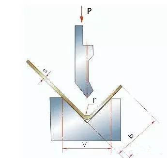
Bending is to use the pressure between the upper and lower die to make the material produce plastic deformation and reach the shape and size we need,working pressure is the pressure required by the bending machine to make the material produce plastic deformation. The influencing factors that determine the working tonnage are: bending radius, bending method, mold ratio, bending length, thickness and strength of bending material, etc., as shown in Figure 1. Generally, the working tonnage can be selected according to the following table. It should be noted that;
(1)The value in the table is the bending pressure when the bending length is one meter: for example S=4mm L=1000mm V=32mm,according to the table P=330kN
(2)The values in this table are calculated on the basis of materials with strength σ B = 450N / mm2. When bending other different materials, the bending pressure should be the data in the table multiplied by the following coefficient;
bronze:0.5;
Stainless steel :1.5;
Aluminum:0.5 ;
Chromium molybdenum alloy steel:2.0。
(3)Approximate calculation formula of bending pressure
Below is the bending pressure comparison table
2. Basic knowledge of bending
2.1 Common bending die
The common bending die is shown as follows. In order to prolong the life of the die, the corner of the bending angle should be rounded as much as possible.
If the bending height is too small, even if the bending die is used, it is not conducive to forming. Generally, the bending height L ≥ 3T (including wall thickness). Generally, the opening width of the V-groove of the lower die is selected according to v = 6T (t is the material thickness).
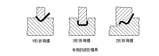
The shape of common bending die is shown in the figure below. The bending die should be selected according to the shape and size of the workpiece. Generally, there are many kinds of bending dies in processing factories, especially those large-scale specialized sheet metal processing factories,in order to process various complex bending parts, these factories have purchased and accumulated many bending dies in various shapes and sizes.
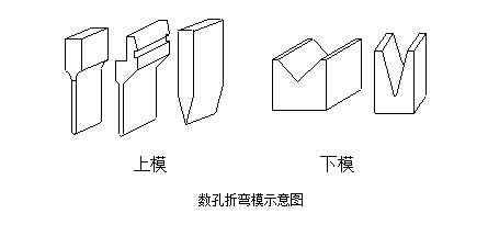
There are many factors that affect the accuracy of bending dimension, such as arc radius of upper die, material, plate thickness, strength of lower die, opening dimension of lower die and so on. In order to meet the needs of various shapes and sizes of the products, under the condition of ensuring the safety of the bending machine, the professional die manufacturers have serialized the bending die. As a sheet metal fabrication process engineer and bending machine operator , they need to have a good understanding of the existing bending die. As shown in the figure below, the left side is the upper die and the right side is the lower die.
Basic principles of bending sequence:
(1) Bending from inside to outside;
(2) Bending from small to large;
(3) The Special part bended first, then bend the regular shape;
(4) The former process or bending should be no influence or interference to next process or bending.
2.2 bend radius
Sheet metal bending parts have bend radius transition at the bend angle. The bend radius should not be too large or too small, and should be properly selected. If the bending radius is too small, it is easy to crack at the bend corner, and if the bending radius is too large, it is easy to rebound. The preferred bending radius (bending inner radius) of various materials with different thickness is shown in the table below.
Minimum bending radius (mm)
|
Materials |
Annealing state |
Cold work hardening state |
||
|
Bending direction and steel plate fiber direction |
||||
|
vertical |
Parallel |
vertical |
Parallel |
|
|
08,10 |
0.1 t |
0.4t |
0.4t |
0.8t |
|
15, 20 |
0.1t |
0.5t |
0.5t |
1.0t |
|
25, 30 |
0.2t |
0.6t |
0.6t |
1.2t |
|
45, 50 |
0.5t |
1.0t |
1.0t |
1.7t |
|
65Mn |
1.0t |
2.0t |
2.0t |
3.0t |
|
aluminum |
0.1t |
0.35t |
0.5t |
1.0t |
|
Red copper |
0.1t |
0.35t |
1.0t |
2.0t |
|
|
|
0.35t |
0.35t |
0.8t |
The data in the above table is the preferred data for reference only. In fact, the radius of upper die manufacturers usually choose 0.3, a small number of manufacturers choose 0.5. For ordinary low-carbon steel plate, antirust aluminum plate, brass plate, copper plate, etc., there is no problem in bending the inner radius of 0.2, but for some high-carbon steel, duralumin, super duralumin, this kind of bending fillet will lead to bending fracture or outer fillet cracking.
2.3 Bending rebound
Rebound angle Δα = B-A,
In the formula, B is the actual angle of the workpiece after springback; a is the angle of the die.
See the table below for the size of the rebound angle and the rebound angle when the single angle is 90 degrees free bending.
Springback angle in 90 degree free bending
|
Material |
r/t |
Material thickness t(mm) |
||
|
<0.8 |
0.8~2 |
>2 |
||
|
Mild steel, brass, σb=350Mpa aluminum, zinc |
<1 1~5 >5 |
4° 5° 6° |
2° 3° 4° |
0° 1° 2° |
|
Medium carbon steel-σb=400-500MPa Hard brass-σb=350-400MPa Hard bronze-σb=350-400MPa |
<1 1~5 >5 |
5° 6° 8° |
2° 3° 5° |
0° 1° 3° |
|
High carbon steel |
<1 1~5 >5 |
7° 9° 12° |
4° 5° 7° |
2° 3° 6° |
Factors affecting rebound and measures to reduce rebound
(1)Mechanical properties of materials: the size of the rebound Angle is proportional to the yield strength of the material and inversely proportional to the elastic modulus E. For precision sheet metal parts , in order to reduce springback, materials should try to choose low carbon steel, not high carbon steel.
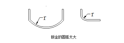
(2)The greater the relative bending radius r/t indicates the smaller the deformation degree, the greater the springback Angle Δα. This is an important concept. The radius R of sheet metal bending should be as small as possible when the material properties allow, which is conducive to improving the accuracy. Special attention: try not to design a large bending radius, as shown in the figure below. Such a large bending radius has great difficulty for quality control.
2.4 Calculation of the minimum bending edge height of a bend
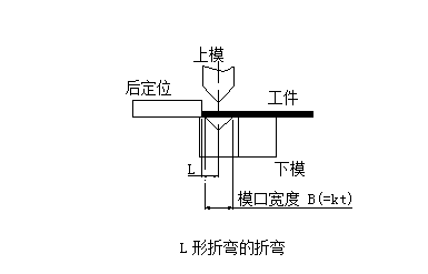
The preparation status of L-Bend during bending is shown in the following figure:
Reference table for bending inner radius R and minimum bending height of cold rolled sheet steel
|
Serial number |
Material thickness |
Lower die opening |
R radius of upper die |
Minimum bend edge height |
|
1 |
0.5 |
4 |
0.2 |
3 |
|
2 |
0.6 |
4 |
0.2 |
3.2 |
|
3 |
0.8 |
5 |
0.8 or 0.2 |
3.7 |
|
4 |
1.0 |
6 |
1 or 0.2 |
4.4 |
|
5 |
1.2 |
8(or 6) |
1 or 0.2 |
5.5(0r 4.5) |
|
6 |
1.5 |
10(or 8) |
1 or 0.2 |
6.8 (or 5.8) |
|
7 |
2.0 |
12 |
1.5 or 0.5 |
8.3 |
|
8 |
2.5 |
16(or 14) |
1.5 or 0.5 |
10.7 (or 9.7) |
|
9 |
3.0 |
18 |
2 or 0.5 |
12.1 |
|
10 |
3.5 |
20 |
2 |
13.5 |
|
11 |
4.0 |
25 |
3 |
16.5 |
The preparation status of z-bend bending is shown in the following figure
The minimum bending dimension L corresponding to z-bend parts with different material thickness is shown in
the table below:
Minimum height of bend edge of z-type bending(mm)
|
Serial number |
Material thickness |
Opening width of lower die |
Upper die radius (R) |
Bending Height of z-type bending |
|
1 |
0.5 |
4 |
0.2 |
8.5 |
|
2 |
0.6 |
4 |
0.2 |
8.8 |
|
3 |
0.8 |
5 |
0.8 or 0.2 |
9.5 |
|
4 |
1.0 |
6 |
1 or 0.2 |
10.4 |
|
5 |
1.2 |
8 (or 6) |
1 or 0.2 |
11.7 (or 10.7) |
|
6 |
1.5 |
10 (or 8) |
1 or 0.2 |
13.3 (or 12.3) |
|
7 |
2.0 |
12 |
1.5 or 05. |
14.3 |
|
8 |
2.5 |
16 (or 14) |
1.5 or0.5 |
18.2(or 17.2) |
|
9 |
3.0 |
18 |
2 or 0.5 |
20.1 |
|
10 |
3.5 |
20 |
2 |
22 |
|
11 |
4.0 |
25 |
3 |
25.5 |
3. A fast calculation method for Developed length of sheet metal bending parts
When a sheet metal bending part is developed, one side of the material will be stretched and the other side will be compressed. The influencing factors include: material type, material thickness, material heat treatment and angle of processing bending.
Calculation principle of development length:
3.1 In the process of steel plate bending, the outer layer is subject to tensile stress, and the inner layer is subject to compressive stress. There is a neutral layer between tensile stress and compressive stress that is neither under tension nor under pressure; The length of the neutral layer does not change in the bending process and before bending, so the neutral layer is the basis for calculating the development length of the bending part
3.2 The position of the neutral layer is related to the deformation degree of the steel plate. When the bending radius (R) is large and the bending angle is large, the deformation degree is small, and the position of the neutral layer is close to the central layer of the thickness of the steel plate; When the bending radius (R) decreases and the bending angle decreases, the deformation degree increases, and the position of the neutral layer moves towards the inner side of the bending center. The distance between the neutral layer and the inner side of the steel plate is expressed by λ.
The above is the most basic knowledge and experience about sheet metal bending, suitable for the assistant engineer just engaged in sheet metal processing, as well as sheet metal workers. In order to make precise and stable sheet metal products, in addition to advanced sheet metal processing equipment, such as laser cutting machine, CNC bending machine, number of welding workers, but also a reasonable process and strict quality control system.

