
Machining Process Analysis and Special Fixture Design
for Thin‑Walled Stainless Steel Sleeve‑Type Parts
1.Part Structure Analysis
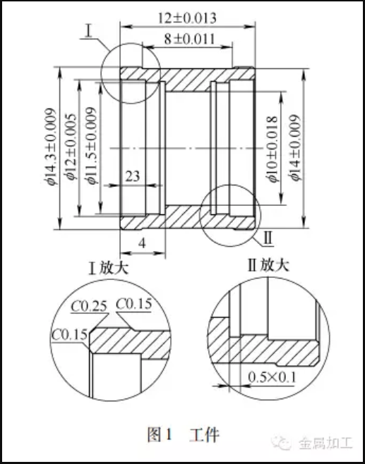
As shown in Figure 1, this component is a typical small‑sized, thin‑walled rotational part. The material is Y1Cr17 (GB/T 1220) stainless steel, supplied as bar stock, and it is intended for mass production.
Main structural
features:
- Minimum wall thickness: 1 mm
- Inner diameter: Φ10–Φ12 mm, with
tolerance 0.01–0.02 mm
- Outer diameter: Φ14–Φ13 mm, with
tolerance 0.02 mm
- Symmetrical inner bores at both ends,
each with an internal groove of 0.5 mm × 0.1 mm
- Several fillets with very small radii,
ranging from 0.15 to 0.25 mm
This part presents
four major difficulties: thin walls prone to deformation, high precision
requirements, compact structure, and poor machinability of the material.
These demand stringent process planning and tooling design.
2.Process Difficulties and Corresponding
Control Measures
2.1 Thermal
Deformation Caused by Cutting Heat
Thin‑walled
workpieces have low thermal capacity and slow heat conduction. Cutting heat can
cause rapid temperature rise, making dimensional control extremely difficult.
Countermeasures:
- Reduce cutting deformation and cutting
forces to minimize heat generation at the source.
- Increase the heat dissipation area of
the cutting edge and ensure an ample supply of cooling and lubricating
fluid.
- Use emulsions containing sulphur‑ or
chlorine‑based extreme‑pressure additives to provide both anti‑adhesion
and cooling performance.
- Maintain sufficient flow rate and
pressure of the cutting fluid.
2.2 Vibration and
Deflection Under Cutting Forces
Radial cutting
forces tend to bend the workpiece. In addition, fluctuating chip‑breaking
forces can excite vibration in the tool‑workpiece system, adversely affecting
dimensional accuracy, form and position tolerances, and surface finish.
Countermeasures:
- Select machine tools with high rigidity
and adequate power.
- Increase the stiffness of the tool and
workpiece system – for example, by enlarging the tool shank cross‑section
and minimizing tool overhang.
- Optimize tool geometry (e.g., increasing
rake angle) to reduce cutting forces.
2.3 Clamping
Deformation
When a three‑jaw
self‑centering chuck is used, radial clamping forces can easily deform the thin
wall into a triangular shape, causing roundness errors. If clamping force is
reduced too much, the workpiece may become loose during machining.
Limitations of
conventional methods:
- Using open transition rings or
increasing the jaw contact area – suitable only for relatively thicker
walls and simpler geometries.
- Axial clamping (via a nut) – despite
minimal deformation, the lengthy auxiliary setup time makes it unsuitable
for high‑volume production.
Therefore, a
dedicated fixture must be designed to simultaneously ensure accuracy and
productivity.
3.Special Fixture Design
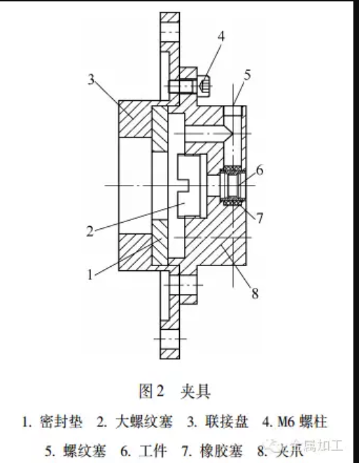
3.1 Locating
Datums and Clamping Method
- Radial datum: the pre-machined outer
diameter Φ(14.3 ± 0.009) mm. Axial datum: the finished left end face.
- Axial datum: the finished left end face.
Because the wall
thickness is only 1 mm, the cutting allowances, cutting forces, and clamping
forces must all be kept moderate. Hence, a pneumatic elastic rubber
fixture is adopted, as shown in Figure 2.
3.2 Fixture
Structure and Working Principle (Figure 2)
The fixture consists
of a connecting plate, sealing gasket, large‑thread plug, M6 studs, threaded
plug, rubber plug, etc.
The connecting plate is mounted on the machine spindle. Its central hole (Φ20
mm) is connected to the compressed‑air line of a rotary pneumatic device.
Compressed air passes through three symmetrically arranged air passages and
acts on the elastic rubber sleeve, which expands uniformly to clamp the
workpiece.
The locating holes for the gripper jaws are machined after the fixture has been
properly installed on the machine, ensuring concentricity with the spindle.
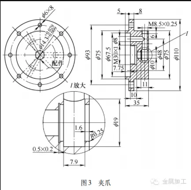
3.3 Gripper Jaw
(Figure 3)
The gripper jaw is
the main actuating element. Its structural design must ensure uniform elastic
deformation and high repeated positioning accuracy. Detailed dimensions are
given in Figure 3 (drawing omitted here).
4.Selection of Tool Materials and
Cutting Parameters
4.1 Tool Materials
Y1Cr17 is a ferritic
free‑cutting stainless steel. Its machinability is comparable to that of free‑cutting
structural steels, while its mechanical properties are similar to those of high‑quality
structural steels.
- Drills, taps, and other standard tools:
use advanced high‑speed steels such as W12Cr4V4Mo, W12Cr4V5Co5
(T15), and W9Cr4V5Co3.
- Turning tools (external and internal):
select cemented carbide grades YG, YW1, YW2, YH1, YH2, or PVD‑coated
ultra‑fine grain cemented carbide and PVD‑coated cermet.
Tool
geometry (a larger rake angle reduces cutting forces, while a moderate
clearance angle maintains edge strength):
|
Operation |
Rake angle γ₀ |
Clearance angle α₀ |
|
Rough turning |
12°–20° |
6°–10° |
|
Finish turning |
20°–30° |
10°–20° |
4.2 Cutting
Parameters
|
Operation |
Depth of cut (mm) |
Feed rate (mm/r) |
Cutting speed
(m/min) or spindle speed (r/min) |
|
Rough turning (OD) |
0.3–0.5 |
0.02–0.05 |
approx. 3000 r/min |
|
Finish turning
(OD) |
0.1–0.15 |
0.02–0.05 |
approx. 3000 r/min |
|
Rough boring (ID) |
0.2–0.3 |
0.02–0.05 |
approx. 3000 r/min |
|
Finish boring (ID) |
0.1–0.15 |
0.02–0.05 |
approx. 3000 r/min |
|
Grooving / Parting
off |
— |
0.02 |
approx. 2000 r/min |
|
Drilling (Φ9.5 mm) |
— |
0.07 |
approx. 1200 r/min |
Note: When
using ultra‑fine grain cemented carbide or PVD‑coated tools, cutting speeds can
exceed 295 m/min. Within the machine’s speed capability, the highest
possible spindle speed should be selected to improve efficiency.
4.3 Cutting Fluid
Selection
For thin‑walled
workpieces, cutting fluids that provide both cooling and lubrication are
preferred. Recommended types include sulphurized oil, sulphurized soybean oil,
kerosene mixed with oleic acid or vegetable oil, carbon tetrachloride mixed
with mineral oil, and high‑concentration emulsions.
5.Recommended Process Sequence
Operation I (bar
stock clamping):
- Drill a Φ9.5 mm pilot hole.
- Rough bore the inner hole.
- Rough and finish turn both end faces to
size.
- Rough turn the outer diameter.
- Semi‑finish turn the external profile.
- Finish turn the external profile to
drawing requirements.
- Part off.
Operation II
(special fixture clamping):
- Semi‑finish and finish turn the inner
bore and end face of one end to size.
- Cut the internal groove.
- Reverse the workpiece; semi‑finish and
finish turn the inner bore and end face of the other end.
- Cut the internal groove on that side.
6.Conclusions
By employing the
pneumatic elastic rubber fixture in conjunction with appropriate tool materials
and cutting parameters, the deformation problems caused by clamping forces,
cutting forces, and thermal effects have been effectively mitigated, while
simultaneously ensuring high production efficiency suitable for mass
production. In practice, the following points should also be observed:
- Regularly inspect the elasticity and
sealing performance of the rubber sleeve.
- Strictly control the cutting fluid
supply to avoid sudden temperature rises.
- Leave sufficient semi‑finishing
allowance before finish machining to compensate for deformation caused by
stress release.
