
Practical
Operation Guidelines for Turning Slender Shafts
Preface
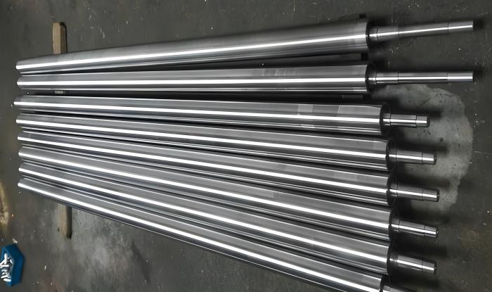
There is a well-known saying in the
machinery processing industry: "Lathe operators dread turning slender
bars, milling operators dread milling flat plates, and fitters dread deep hole
drilling." The term "slender bars" herein refers to slender
shafts. Slender shafts feature a large overhang length, and during turning
operations, they are subjected to four major loads—cutting force, centrifugal
force, clamping force, and gravity. Coupled with cutting heat, these loads
easily induce bending deformation, resulting in machining defects such as tool
marks, taper errors, barrel-shaped distortion, bamboo-joint ripples, and
triangular out-of-round cross-sections. This makes it extremely difficult to
guarantee dimensional accuracy. If the slender shaft requires additional
machining such as trapezoidal thread cutting, its structural rigidity will
further decline. Therefore, turning slender and ultra-slender shafts is a
rigorous test of a lathe operator’s comprehensive technical proficiency and is
regarded as a landmark skill of master lathe workers. Drawing on years of
practical experience with conventional lathes, this paper systematically sorts
out a full set of process control points for slender shaft machining.
1. Definition Classification of Slender
Shafts
A shaft with a length-to-diameter ratio L/d
≥ 25 is defined as a slender shaft; conventional slender shafts satisfy 25 < L/d ≤ 50, while ultra-slender shafts fall within the range 50 < L/d ≤ 100. In actual production, workpieces with a
length-to-diameter ratio of 25 to 50 are the most common, whereas ultra-slender
shafts with a ratio of 50 to 100 pose higher individual machining difficulty
and require lathes with matching travel ranges for processing.

2. Main Causes of Deformation During
Slender Shaft Turning
- The workpiece has an elongated thin profile with extremely low
inherent rigidity;
- Poor heat dissipation in the cutting zone leads to significant
thermal deformation;
- High-speed rotation of the workpiece generates strong
centrifugal force that aggravates vibration;
- The large axial dimension of the workpiece results in long
cutting travel and cumulative tool wear.

3. Nine Core Control Points for Slender
Shaft Turning
Based on years of hands-on experience with
conventional lathes, stable machining of slender shafts relies on nine key
procedures:
- Complete self-inspection and calibration of machine tool
accuracy before machining;
- Adopt reverse feed turning from the headstock toward the
tailstock;
- Select special turning tools that are sharp yet possess
sufficient bending resistance;
- Match reasonable cutting parameters;
- Master the clamping process of one-chuck-one-center support;
- Properly deploy auxiliary supports including steady rests,
transition bushings and follow rests;
- Supply sufficient cutting fluid to enhance cooling and
lubrication;
- Divide machining into rough turning, semi-finish turning and
finish turning for sequential processing;
- Implement refined control over every operational detail
throughout the process.

4. Pre-Machining Accuracy Calibration of
Lathes (Case: 6m Long Shaft Machined on CW6130 Conventional Lathe)
The CW6130 is a single-tool-post
conventional lathe with a maximum guide rail travel of 7 meters. Before
machining extra-long slender shafts, the accuracy and operational stability of
the lathe must be inspected item by item.
4.1 Accuracy Inspection of Spindle,
Tailstock and Guide Rail
Use a dial indicator to verify spindle
precision: the radial runout of the centering mandrel shall not exceed 0.01 mm,
and axial endplay shall be controlled within 0.015 mm. The coaxiality between
the tailstock center and spindle shall be ≤ 0.03 mm. The straightness tolerance
of the guide rail is 0.1 mm per meter, ensuring parallelism between the spindle
centerline and tailstock centerline across the full travel range.
- If spindle accuracy exceeds tolerance: adjust and pre-tighten
the clearance of spindle box nuts;
- If guide rail straightness fails to meet standards: the
operator shall compensate for taper errors manually to reduce machining
deformation.
4.2 Troubleshooting and Elimination of
Whole-Machine Vibration Sources
Lathe vibration directly causes chatter
marks and out-of-round defects on workpieces. All vibration sources must be
inspected and rectified:
- Vibration generated by unbalanced motor rotors and uneven
electromagnetic force;
- Dynamic imbalance of chucks, pulleys and workpieces;
- Impact from gear meshing inside the gearbox, uneven thickness
of V-belts, and pulley eccentricity;
- Shock loads during forward and reverse rotation switching via
the clutch;
- External vibration transmitted through the foundation from
other forging equipment, passing vehicles and transport machinery in the
workshop.
For severe vibration, corresponding
corrective actions shall be carried out. Ground vibration from the factory
floor can be isolated by installing expansion joints in the foundation to
create a stable machining environment for the lathe.
5. Workpiece Clamping Processes:
Comparison Between One-Chuck-One-Center and Double-Center Support
Two mainstream clamping methods are adopted
for slender shafts on conventional lathes:
- One-chuck-one-center clamping: One
end of the workpiece is held by a chuck, and the other end is supported by
a tailstock center;
- Double-center clamping: The
workpiece is positioned via center holes on both ends and supported by two
centers.
Both clamping methods deliver high rigidity
and allow large workpiece overhang. Double-center clamping provides superior
coaxial positioning accuracy but lacks sufficient allowance for axial thermal
expansion. It is only suitable for short shafts with a small length-to-diameter
ratio, minimal machining allowance and strict coaxiality requirements. By
contrast, one-chuck-one-center clamping enables axial thermal expansion
compensation and is applicable to the vast majority of slender shaft machining
scenarios, making it the more widely adopted method.

5.1 Operation Specifications for
One-Chuck-One-Center Clamping
- Control of center pre-tightening force: The jacking force shall
be light enough for the workpiece to rotate freely by hand. Adjust the
tailstock handwheel at any time during machining to prevent excessive
thermal jacking force from squeezing the workpiece and inducing
deformation. Optimization tip: Machine and grind center holes to the
maximum feasible size to expand contact area with the center tip, which
preserves positioning accuracy even after long-duration cutting. An
elastic center tip is recommended if conditions permit, as it
automatically compensates for thermal elongation of the workpiece.
- Periodic release of thermal deformation stress: Approximately
every 10 minutes of machining, lightly check center tightness by hand
without stopping the machine. Loosen slightly then re-adjust the jacking
force moderately to release axial thermal expansion stress of the
workpiece. Repeat this operation to eliminate thermal bending.
- Chuck selection: Prioritize four-jaw independent chucks, which
deliver stronger clamping force and four-point positioning to avoid
workpiece displacement. Three-jaw self-centering chucks provide weaker
clamping force and tend to shift after long-term operation. Specifications
for four-jaw chuck clamping: The clamped length of the workpiece shall not
exceed 60 mm; the clamped section must be pre-turned to a smooth surface
for full contact without gaps.
6. Control of Cutting Heat and
Specifications for Cutting Fluid Application
High temperatures generated during cutting
cause axial elongation of the workpiece, resulting in compressive bending—one
of the primary triggers of slender shaft deformation. Cooling requirements are
specified as follows:
- The cutting fluid pump shall provide abundant flow to fully
cover the cutting zone and tool body. High-volume fluid rapidly removes
massive cutting heat to stabilize temperatures of both workpiece and
cutting tool;
- No leakage shall exist in the cooling circulation system. Stop
the machine immediately and replenish cutting fluid if the liquid level
drops below the standard range;
- Cutting fluid selection: Emulsified fluid is used for general
machining; sulfurized cutting oil is adopted for cutting with high-speed
steel tools.
7. Pre-Processing Requirements for
Workpiece Blanks
After clamping the workpiece, inspect the
blank machining allowance and bending degree to determine the cutting depth for
the first rough turning pass:
- The bilateral cutting depth of the first pass shall be
controlled at approximately 5 mm to completely remove the oxidized scale
on the blank. Align the tool height with the workpiece center during tool
setting;
- If the blank features severe bending that cannot meet
processing requirements, straighten the bar stock via hot straightening.
Cold straightening and hammer straightening are strictly prohibited to
avoid residual internal stress;
- Reserve sufficient machining allowance for rough turning. Rough
turning releases inherent blank stress and inevitably introduces workpiece
bending; insufficient allowance will leave deformation uncorrectable in
subsequent finishing processes.
8. Application Process of Steady Rests
and Transition Bushings
8.1 Two Primary Application Scenarios
for Steady Rests
- Steady rests paired with one-chuck-one-center clamping for end
facing, center hole drilling/reaming, and shoulder turning at both ends of
the workpiece;
- Segmented turning of long shafts: The steady rest supports the
middle section of the workpiece, halving the effective support span and
equivalent length-to-diameter ratio. This greatly improves workpiece
rigidity and suppresses bending deformation during cutting.
8.2 Specifications for Transition
Bushings
Pre-turn a supporting outer circle at the
middle of the workpiece, fit the transition bushing onto the surface, then
mount the steady rest for support:
- The roundness of the transition bushing outer surface shall not
exceed 0.02 mm and must be precision-turned on the lathe before use;
- The radial runout of the installed transition bushing shall be
controlled within 0.03 mm to guarantee coaxiality with the spindle.
8.3 Assembly and Adjustment Steps for
Steady Rests
- Secure the steady rest firmly to the lathe bed. With the
workpiece rotating, adjust the two lower support jaws to make uniform
contact with the workpiece supporting surface, then lock the jaws;
- Close the steady rest upper cover, adjust the upper support jaw
to achieve uniform contact with the workpiece, and fasten securely;
- All three support jaws shall bear even pressure with moderate
tightness, and the supporting surface must remain coaxial with the spindle
rotation center.


9 Selection and Operation Key Points of
Follow Rests
Follow rests are fixed on the lathe
carriage and travel longitudinally synchronously with the cutting tool.
Equipped with two or three support jaws, they counteract radial cutting forces
and enhance workpiece rigidity, significantly improving roundness and surface
roughness of long shafts. Follow rests are indispensable auxiliary fixtures for
slender shaft machining.
9.1 Basic Calibration Requirements
Whether two-jaw or three-jaw follow rests
are used, the support center must perfectly coincide with the centers of the
chuck and tailstock center tip.
9.2 Material Matching for Support Jaws
Support jaws can be manufactured from cast
iron, brass, Nylon 1010, bakelite, polyethylene, or bearing rollers for higher
efficiency:
- Cast iron and brass: Suitable for rough turning of outer
diameters with high wear resistance and load capacity;
- Nylon, bakelite and polyethylene: Ideal for finish turning, as
they prevent scratching the workpiece surface.
Calibration method: Clamp a cylindrical
reamer or milling cutter on the chuck to dress the support jaws. Alternatively,
pre-turn a reference outer diameter on the workpiece, perform dry running
contact between all three support jaws and the workpiece, then fine-lap the
jaws with sandpaper to achieve full-surface fitting.
9.3 Advantages of Three-Jaw Follow Rests
Workpiece gravity causes downward bending
during machining; three-jaw follow rests provide omnidirectional balanced
support and are recommended for slender shaft processing. Ensure 80%–90% of
each support jaw contact surface fits the workpiece tightly, and adjust
pressure by tactile feedback:
- Excessively tight support: The workpiece deforms under
extrusion as the tool travels, forming bamboo-joint ripples;
- Excessively loose support: Lack of effective support triggers
vibration, resulting in ovality, triangular out-of-roundness and other
machining errors.
9.4 Matching Specifications for Cutting
Operations
- Position the cutting tool tip as close as possible to the rear
support jaw of the follow rest; the tool tip shall be 0.2 mm higher than
the workpiece centerline;
- When adopting a large cutting depth for rough turning,
continuously measure the workpiece outer diameter with an outside caliper
without stopping the machine, fine-tune support jaw pressure in real time,
and slightly adjust feed rate as required;
- The first rough turning pass primarily removes oxidized scale
and initial blank bending, leading to large dimensional fluctuations.
Stable machining conditions and gradual deformation correction are
achieved from the second and third passes onward;
- Insufficient support pressure eliminates the rigidity-enhancing
effect of follow rests. Over-tight support forces the cutting tool to
penetrate deeper, reducing workpiece diameter and causing the follow rest
jaws to lose contact. Cutting forces then push the workpiece outward and
increase its diameter. This cyclic dimensional variation generates
periodic bamboo-joint ripples. When this defect occurs, retract the tool
and reduce spindle speed by one gear—a standard solution for rough
machining;
- Maintain full concentration throughout machining. Use the right
hand to continuously fine-tune the support jaw handwheel while sensing the
tightness of the tailstock center tip. Frequent pressure adjustments are
required during rough turning due to severe deformation; fewer adjustments
are needed after semi-finish turning as deformation is minimized.
Three-jaw follow rests support higher cutting speeds. Do not
reverse-adjust follow rest supports when using one-chuck-one-center
clamping with reverse feed turning.

10 Process Principle of Reverse Feed
Turning
Machine a relief groove near the headstock
to install a steady rest, then feed the cutting tool longitudinally from the
headstock toward the tailstock—this process is defined as reverse feed turning.
In conventional forward feed turning, the axial jacking force of the tailstock
center aligns with the axial component of cutting force, compounding workpiece
bending. In reverse feed turning, the axial cutting force component applies
tensile stress to the workpiece, stretching the machined section along the same
direction as thermal elongation. Compared with forward feed, reverse feed
delivers superior stability and vibration resistance. Deformation can be
drastically reduced when combined with an elastic center tip.
11 Geometric Parameter Design of Special
Turning Tools for Slender Shafts
A common workshop saying states:
"Turning relies 30% on operator skill and 70% on cutting tools."
Matching tool angles is critical for stable cutting. 90° external turning tools
are the primary choice for slender shaft machining, with angle specifications
as follows:
- Rake angle γ₀: Larger
rake angles suppress vibration. Since slender shaft turning generally
operates at low cutting speeds where rake angle exerts a prominent
influence on vibration, a rake angle γ₀ =
20° is recommended for rough turning, and γ₀ = 25° for finish turning.
- Principal cutting edge angle κᵣ:
With constant cutting depth and feed rate, increasing the principal
cutting edge angle reduces vibration amplitude by lowering radial cutting
force and narrowing effective cutting width. For rough turning of long
shafts, select tools with κᵣ = 75°–80°; for finish
turning, κᵣ = 85°–90° to eliminate or minimize vibration. Where tool
strength permits, maximize the principal cutting edge angle. 90° turning
tools may be used and clamped at 85°–88° for equivalent excellent
performance.
- Clearance angle α₀: Clearance
angle has minor impact on cutting stability under normal conditions.
However, reducing the clearance angle to 2°–3° noticeably suppresses
vibration. Slight flank wear on the tool also creates a significant
damping effect.
- Tool nose radius rₛ:
Larger nose radii amplify radial cutting force and induce self-excited
vibration. Therefore, minimize the nose radius while avoiding excessive
tool wear and poor surface roughness. Recommended nose radius rₛ = 0.5 mm, with chip breaker groove width R1.5–3 mm.
- Supplementary requirements for follow rest turning: Reliable
chip breaking is mandatory to facilitate smooth chip evacuation, as long
continuous chips can severely damage follow rest supports. Tools must
remain sharp to reduce friction between tool and workpiece while retaining
sufficient structural strength. Avoid severely worn carbide inserts, which
may induce instantaneous workpiece bending and secondary tool damage
caused by insert embedding into the workpiece surface.
12. Rational Selection of Three Cutting
Parameters (Turning)
The three core turning parameters are
cutting speed Vc, cutting depth ap, and feed per revolution fn. Proper
parameter matching minimizes machining deformation.
12.1 Cutting Depth ap
With fixed rigidity of the machining
system, increasing cutting depth raises cutting force and cutting heat,
aggravating stress-induced and thermal deformation of long shafts. Adopt
layered cutting with controlled allowance:
- Rough turning: Bilateral total cutting depth ≤ 6 mm;
- Semi-finish turning: Bilateral cutting depth 2–3 mm;
- Finish turning: Bilateral cutting depth 0.5–1 mm.
12.2 Feed rate fn
Increased feed rate thickens chip thickness
and elevates cutting force. For workpieces with sufficient rigidity, raising
feed rate improves efficiency more effectively than increasing cutting depth.
However, slender shafts with low rigidity require small feed rates:
approximately 0.1 mm/r for rough turning, and 0.03–0.05 mm/r for finish
turning.
12.3 Cutting speed Vc
Moderately increasing cutting speed reduces
cutting force and friction-induced deformation by raising cutting temperature.
Excessively high speed generates excessive centrifugal force and destabilizes
cutting. Select a moderate speed range and monitor for follow rest
vibration—reduce spindle speed immediately if chatter occurs. Strictly separate
rough and finish turning passes to minimize cumulative deformation.

13 Standardized Sequential Processing:
Rough Turning, Semi-Finish Turning and Finish Turning
13.1 Rough Turning
The first rough turning pass must fully
remove blank oxidized scale. Do not stop the machine mid-process if steady
rests operate normally. Continuously monitor workpiece outer diameter with an
outside caliper and slightly reduce feed rate to compensate for gradual tool
wear. Surface roughness after rough turning reaches Ra12.5. Retract the tool
and lower spindle speed by one gear if bamboo-joint ripples, spiral grooves or
chatter marks appear. Rough turning releases blank internal stress and
inevitably introduces workpiece bending, so sufficient allowance must be
reserved for subsequent semi-finish and finish turning.
13.2 Semi-Finish Turning
Replace rough turning tools with finishing
inserts and install upgraded follow rest support jaws, then repeat all rough
turning procedures for cutting. Deformation is significantly reduced after
semi-finish turning, with surface roughness reaching approximately Ra6.3. For
safety, semi-finish turning may be split into two or three passes. For long
lead screw shafts with trapezoidal threads, semi-finish outer diameter turning
adopts two stages: first rough-turn to form the thread profile, rough-cut the
thread root diameter with high-speed steel tools while leaving machining
allowance, rough-turn both sides of the trapezoidal thread with residual
allowance, then perform a second semi-finish pass on the outer cylinder.
13.3 Finish Turning
Low-speed finish turning allows free
mid-process shutdown for dimensional measurement and minor feed rate
adjustment, facilitating precise dimensional control yet yielding inferior
surface quality. In mass production, YT15 carbide inserts with excellent hot
hardness and wear resistance are adopted for high-speed cutting, achieving
dimensional accuracy Grade 6 and surface roughness Ra1.6 or superior. If the
lathe is equipped with an electric polishing wheel, post-polishing can further
reduce surface roughness to Ra0.6 or below.
14 Conclusion
The core logic for deformation control in
slender shaft machining can be summarized as follows: boost workpiece rigidity
via steady rests and follow rests; reduce cutting force by optimizing tool
geometry, small cutting depths and low feed rates; counteract thermal
deformation through reverse feed turning, elastic center tips, periodic thermal
stress relief and full-flow cooling; eliminate internal stress via multi-stage
rough, semi-finish and finish turning; remove all vibration sources through
machine tool accuracy calibration and dynamic balance correction. Mastery of
the complete set of process points outlined above enables stable machining of
all types of slender shafts and extra-long lead screws on both conventional and
CNC lathes.
