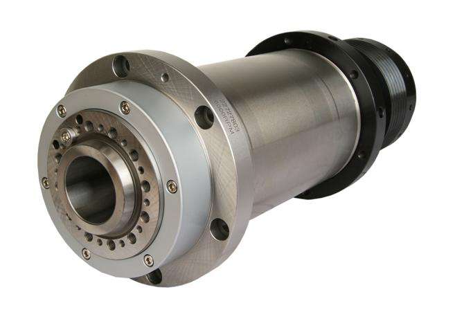
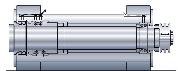
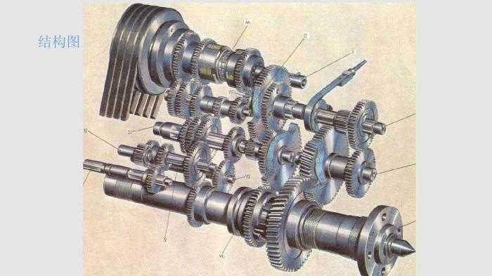
In practice, the structural shape of parts varies greatly, but the basic geometric composition is nothing more than the outer circle, inner hole, plane, thread, tooth surface, curved surface, etc. Few parts are composed of a single typical surface, which is often composed of some typical surfaces. The machining method is more complex than that of a single typical surface, which is a comprehensive application of typical surface machining methods. The following describes the typical machining technology of shaft parts.

First: Machining of shaft parts
1. Classification and technical requirements of shaft parts
Shaft is one of the typical parts in machining. It is mainly used to support gears, pulleys, cams, connecting rods and other transmission parts in machinery to transmit torque. According to different structural forms, the shaft can be divided into step shaft, taper mandrel, optical shaft, hollow shaft, crankshaft, camshaft, eccentric shaft, various lead screws and so on. The step drive shaft is widely used, and its processing technology can comprehensively reflect the processing law and commonness of shaft parts.
According to the function and working conditions of shaft parts, the technical requirements are mainly in the following aspects:

(1) Dimensional accuracy: the main surfaces of shaft parts are usually divided into two categories: one is the outer round journal matched with the inner ring of the bearing, i.e. the supporting journal, which is used to determine the position of the shaft and support the shaft, with high dimensional accuracy requirements, usually it 5 ~ it7; the other is the journal matched with various transmission parts, i.e. the matching journal, with slightly lower accuracy, usually it 6 ~ it9.
(2) Geometric accuracy: mainly refers to the roundness and cylindricity of the important surfaces such as journal surface, external cone surface and taper hole. Generally, the error shall be limited within the dimension tolerance range. For the precision shaft, the geometric accuracy shall be specified separately on the part drawing.
(3) Mutual position accuracy: including coaxiality of internal and external surfaces, important shaft surfaces, radial runout of circles, perpendicularity of important end faces to axis lines, parallelism between end faces, etc.
(4) Surface roughness: the machining surface of the shaft has the requirement of roughness, which is generally determined according to the possibility and economy of machining. The supporting journal is usually 0.2-1.6 μ m, and the matching Journal of transmission parts is 0.4-3.2 μ M.
(5) Others: heat treatment, chamfering, chamfering and appearance modification.
The second: Materials, blanks and heat treatment of shaft parts
1. Materials of shaft parts
(1) Materials of shaft parts: 45 steel(EN C45, ASTM 1045) is commonly used, 40Cr(DIN EN10083-1 41Cr4/42Gr4, ASTM A29M 5140) GCr15 bearing steel, 65Mn spring steel and nodular cast iron can be used for shafts with high precision; 20CrMnTi, 20mn2b, 20Cr and other low carbon alloy steel or 38CrMoAl nitriding steel can be used for shafts with high speed and heavy load.
(2) Shaft blank: commonly used round bars and forgings; large shafts or shafts with complex structure adopt castings. After heating and forging, the fiber structure in the metal can be evenly distributed along the surface to obtain high tensile, bending and torsional strength.
(3) Heat treatment of shaft parts
For the forging blank, before machining, normalizing or annealing treatment shall be arranged to refine the grain inside the steel, eliminate the forging stress, reduce the hardness of the material and improve the cutting performance.
Quenching and tempering are generally arranged after rough turning and before semi finish turning to obtain good physical and mechanical properties.
Surface quenching is usually arranged before finishing machining, which can correct the local deformation caused by quenching.
For shafts with high precision, low temperature aging treatment is needed after local quenching or rough grinding.

The third: Clamping method for machining shaft parts
There are three main clamping methods for machining shaft parts
(1) Positioning and clamping with two central holes
Generally, the central hole is machined with the important outer circular surface as the positioning rough datum, and then the central hole at both ends of the shaft as the precise datum; the datum shall be unified, the datum shall be overlapped, and each other shall be the datum as far as possible, and multiple surfaces shall be machined in one installation.
The central hole is a unified positioning and inspection datum for workpiece machining, its own accuracy is very important, and its preparation work is relatively complex. The processing of the central hole often uses the support journal positioning to turn (drill) the central cone hole; Then the center hole is used to locate and finish turning the outer circle; the outer circle is used to locate and rough grind the taper hole; the center hole is used to locate and finish grinding the outer circle; finally, the supporting journal outer circle is used to locate and finish grinding (scraping or grinding) the taper hole, so that the accuracy of the taper hole can meet the requirements.
(2) For hollow shaft or short shaft and other parts that can not be located with the center hole, the outer circle surface of the shaft can be used to locate, clamp and transfer the torque. Generally, three claw chuck, four claw chuck and other general clamps, or various high-precision automatic centering special clamps, such as liquid plastic thin-wall centering clamp, diaphragm chuck, etc.
When machining the outer circle surface of hollow shaft, various plugs with central hole or pull rod mandrel are often used to install the workpiece. Plug is often used for small taper hole and pull rod mandrel with plug is often used for large taper hole, as shown in Fig. 6-2.
The fourth: Process example of shaft parts
1. Technical requirements and functions of
CA6140 lathe spindle
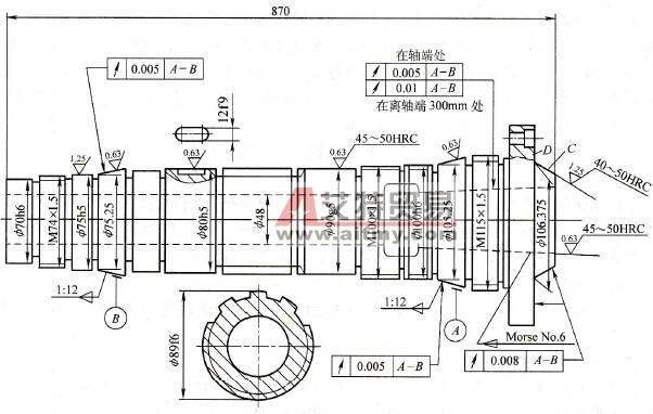
Figure 6-3 is the schematic diagram of main shaft parts of CA6140 lathe.
It can be seen from the parts diagram that the main shaft is in the form of steps, on which are the cylindrical and conical surfaces for the installation of bearing and transmission parts, the spline positions for the installation of sliding gear, the internal and external conical surfaces for the installation of chuck and center, the spiral surfaces for the connection of fastening nuts, and the deep holes through the bar, etc. The functions and technical requirements of the main parts of the spindle are introduced as follows:
(1) Supporting Journal: the roundness tolerance of two supporting journals A and B of the main shaft is 0.005mm, and the radial run out tolerance is 0.005mm; while the contact rate of 1:12 cone surface of the supporting journal is ≥ 70%; the surface roughness Ra is 0.4mm; the size accuracy of the supporting journal is it5. Because the Journal on the main shaft is used to install the bearing and is the assembly datum of the main shaft components, its machining accuracy directly affects the rotation accuracy of the main shaft components.
(2) End taper hole: the runout tolerance of the inner taper hole (Mohs No.6) at the end face of the shaft relative to the center of the supporting Journal A and B is 0.005mm, and the tolerance is 0.01mm at 300 mm from the end face of the shaft; the contact rate of the taper surface is ≥ 70%; the surface roughness Ra is 0.4mm; the hardness is required to be 45 ~ 50HRC. The taper hole is used to install the center or taper handle tool, and its axis line must be strictly coaxial with the axis lines of two supporting journals, otherwise the workpiece (or tool) will have coaxiality error.
(3) End short cone and end face: the radial circular runout tolerance of the head short cone C and end face d with respect to the two supporting journals a and B of the main shaft is 0.008mm; the surface roughness Ra is 0.8mm. It is the position surface of the mounting chuck. In order to ensure the centering accuracy of the chuck, the conical surface must be coaxial with the bearing journal, and the end face must be perpendicular to the rotation center of the main shaft.
(4) Loose gear Journal: the radial circular runout tolerance of loose gear journal to supporting journals a and B is 0.015 mm. As the journal is the surface matching with the gear hole, there should be a certain degree of coaxiality requirements relative to the supporting journal, otherwise it will cause poor engagement of the main shaft drive, and when the main shaft speed is very high, it will affect the stability of the gear drive and generate noise.
(5) The error of the screw surface on the thread spindle is one of the reasons for the end face runout of the compression nut, so the machining accuracy of the thread should be controlled. When the face runout of the compression nut on the main shaft is too large, the axis line of the inner ring of the pressed rolling bearing will tilt, thus causing the radial circle runout of the main shaft.
2.Main points and measures of spindle machining
The key of spindle machining is how to ensure the size, geometry, position accuracy and surface roughness of the bearing journal of the spindle, the geometric accuracy, surface roughness of the inner and outer conical surfaces of the front end of the spindle and their position accuracy for the bearing journal.
The precision grinding method can be used to ensure the dimensional accuracy, geometric accuracy and surface roughness of the main bearing journal. Before grinding, the precision of the precise positioning datum should be improved.
To ensure the geometric accuracy and surface roughness of the inner and outer conical surfaces of the front end of the spindle, the same method of precision grinding should be used. In order to ensure the position accuracy of the external cone surface to the supporting journal and the position accuracy between the supporting journals, the combined grinding method is usually used to process these surfaces in one-time clamping, as shown in Figure 6-4. There are two independent grinding wheel racks on the machine tool, and the finishing grinding is carried out in two stations. Station I is used to finish grinding the front and rear journal conical surfaces, and Station II is used to grind the front bearing surface and short conical surface of the main shaft with angle forming grinding wheel.
The position accuracy of the main shaft taper hole relative to the supporting journal is ensured by grinding the taper hole with the supporting Journal A and B as the positioning reference on the grinder. The bearing journal is used as the positioning datum to process the inner cone, which conforms to the principle of datum coincidence. Before final grinding the front end taper hole, the bearing journal a and B as the positioning reference should reach a certain accuracy. The special device is generally used for grinding the taper hole of the main shaft, as shown in Fig. 6-5. The clamping device is composed of base 1, support 2 and floating collet 3. The two supports are fixed on the base. As the positioning datum of the workpiece, two sections of journal are placed on two V-shaped blocks of the support. The V-shaped blocks are inlaid with cemented carbide to improve wear resistance and reduce scratches on the workpiece Journal. The center height of the workpiece should be exactly equal to the center height of the grinding wheel shaft of the grinding head, otherwise, the taper hole bus will be Hyperbola, which affects the contact accuracy of inner cone hole. The floating clamp head at the rear end is installed in the taper hole of the grinding machine spindle with a taper handle, the end of the workpiece is inserted in the elastic sleeve, the floating clamp head shell and the workpiece are pulled to the left with a spring, and the end face of the taper handle inlaid with carbide is pressed by a steel ball to limit the axial movement of the workpiece. With this fixing method, the positioning accuracy of the workpiece bearing journal can not be affected by the spindle rotation error of the internal grinder, and the influence of the machine vibration on the machining quality can also be reduced.
The machining of the surface of the outer circle of the main shaft should take the center hole as a unified positioning datum. However, in the machining of the main shaft, when the inner through-hole is machined, the central hole as the positioning reference cannot be reused . At this time, the cone with the central hole is often used to block the holes at both ends of the main shaft, as shown in Figure 6-2, so that the central hole of the cone plug plays the role of additional positioning reference.


